NSX Integration
At this point, I now have a functioning vSphere environment. Key components of vSphere include the ESXi hypervisor and vCenter Server. Both of which are now up & running in my Homelab that has only one Dell PowerEdge R740 server, a tiny TP-Link 5-Port Gigabit switch, and a Raspberry PI. The switch is connected to my main switch and to the NIC ports of the R740. The Raspberry PI functions as a router, DNS, NTP and VPN server.
I am now going to deploy a NSX Manager and two Edge Node VM’s in my Homelab.
I have downloaded the NSX Unified Appliance OVA.
nsx-unified-appliance-4.2.1.3.0.24533887.ova
I followed the official NSX Quickstart guide to install it.
⚠️FYI. There’s some deviation from the Quickstart Installation because I’m using a single ESXi host and I need to connect the Edge Nodes to separate segments and use different uplink profiles. This is reflected in Step 4.
The NSX Policy API is the default mode, and that is fine and I won’t change it to Manager mode. Later on, I will create the objects using Policy API and so I will use Policy API when I install the TKGI tile.
To prepare for the installation, I filled out this table with the planned network settings.
| Setting | Notes | Your Value |
|---|---|---|
| VLAN 11 | For management traffic | 192.168.86.0/24 |
| VLAN 12 | For NSX overlay traffic | 192.168.20.0/24 |
| VLAN 50 | For traffic between the tier-0 gateway and physical router | 192.168.50.0/24 |
| PG-mgmt | VC dvportgroup backed by VLAN 11 (management VLAN) | “VM Network” |
| Management subnet | 192.168.10.0/24, default gateway: 192.168.10.1, subnet mask: 255.255.255.0 | 192.168.86.0/24, default gateway: 192.168.86.1, subnet mask: 255.255.255.0 |
| TEP (tunnel endpoint) subnet | 192.168.20.0/24, default gateway: 192.168.20.1, subnet mask: 255.255.255.0 | 192.168.20.0/24, default gateway: 192.168.20.1, subnet mask: 255.255.255.0 |
| VC IP address | 192.168.10.10 (VLAN 11) | 192.168.86.101 (VLAN 11) |
| ESXi-1 IP address | 192.168.10.11 (VLAN 11), 192.168.20.11 (VLAN 12) | 192.168.86.23 (VLAN 11), 192.168.20.11 (VLAN 12) |
| NSX-mgr-1 IP address | 192.168.10.14 (VLAN 11) | 192.168.86.251 (VLAN 11) |
| Edge-1 IP address | 192.168.10.17 (VLAN 11), 192.168.20.17 (VLAN 12) | 192.168.86.252 (VLAN 11), 192.168.20.17 (VLAN 12) |
| Edge-2 IP address | 192.168.10.18 (VLAN 11), 192.168.20.18 (VLAN 12) | 192.168.86.253 (VLAN 11), 192.168.20.18 (VLAN 12) |
| Physical router’s downlink IP address | 192.168.50.1 (VLAN 50) | 192.168.50.1 (VLAN 50) |
| Tier-0 gateway’s external interface IP address on Edge-1 | 192.168.50.11 (VLAN 50) | 192.168.50.11 (VLAN 50) |
| Tier-0 gateway’s external interface IP address on Edge-2 | 192.168.50.12 (VLAN 50) | 192.168.50.12 (VLAN 50) |
| Tier-0 gateway’s virtual IP (VIP) | 192.168.50.13 (VLAN 50) | 192.168.50.13 (VLAN 50) |
| Segment 1 subnet | 10.1.1.0/24 | 10.1.1.0/24 |
| Segment 2 subnet | 10.1.2.0/24 | 10.1.2.0/24 |
| Segment 3 subnet | 10.2.1.0/24 | 10.2.1.0/24 |
| Test-VM-1 IP address | 10.1.1.11 | 10.1.1.11 |
| Test-VM-2 IP address | 10.1.2.11 | 10.1.2.11 |
| Test-VM-3 IP address | 10.2.1.11 | 10.2.1.11 |
Step 1: Deploy the NSX Manager
The NSX manager VM is deployed through VC’s Deploy OVF Template wizard.
- In VC, right click Cluster and select Deploy OVF Template.
-
Follow the prompts and provide the following information.
Location of the ova file The location where you downloaded the ova file. Virtual machine name NSX-mgr-1 Location for the VM Cluster Compute resource 192.168.86.23 (ESX-1’s IP address) Deployment configuration Medium Storage datastore1 Virtual disk format Thin Provision Network 1 VM Network IP allocation Static Manual IP protocol IPv4 Hostname nsx-mgr-1.deephackmode.io Rolename NSX Manager Default IPv4 Gateway 192.168.86.34 Management Network IPv4 Address 192.168.86.251 Management Network Netmask 255.255.255.0 DNS Server list 192.168.86.34 NTP Server list 192.168.86.34 - Wait for the deployment to finish. The Recent Tasks panel at the bottom of the vSphere Client window will indicate when the task is complete.
- Power on the NSX Manager VM.
- Set up the DNS record for the NSX Hostname.
-
Log in to NSX-mgr-1 at
https://nsx-mgr-1.deephackmode.io.
- Go to System->Licenses and click Add to add your NSX license.
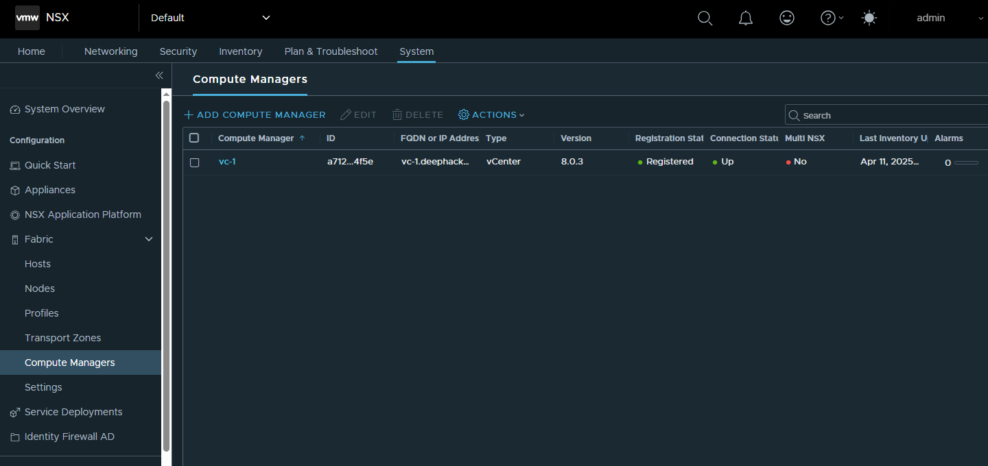
- Go to System->Fabric->Compute Managers and click Add to add the VC as a compute manager. Follow the prompts and provide the necessary information about the vCenter.
- Click Add at the warning Thumbprint is Missing.
-
Wait until Registration Status is Registered. You can click Refresh to refresh the status.
Step 2: Configure a VDS
You can use an existing VDS or configure a new one. If you use an exising VDS, you must set its MTU to 1600 or higher.
Create a VDS in VC
- In VC, under Networking, right click the datacenter and select Distributed Switch->New Distributed Switch.
-
Follow the prompts and provide the following information.
Name VDS-NSX Location Datacenter Spefify a distributed switch version Select the version for your vSphere environment. Number of uplinks 1 Network I/O Control Enabled - After VDS-NSX is created, right click it and select Add and Manage Hosts.
- Select the ESXi host (192.168.86.23).
- In the Manage physical adapters step, for each host, map vmnic1 to Uplink 1 (the default uplink name) on VDS-NSX.
Change the MTU value for VDS-NSX
- In VC, under Networking, right click VDS-NSX and select Settings->Edit Settings.
- In the MTU (Bytes) field, enter 1600.
Create a port group in VDS-NSX
- In VC, under Networking, right click VDS-NSX and select New Distributed Port Group.
-
Provide the following information.
Name PG-all-VLAN VLAN type VLAN trunking VLAN trunk range 0-4094
Step 3: Create an Uplink Profile and Configure Host Transport Nodes
Create an uplink profile
- In NSX Manager, go to System->Fabric->Profiles->Uplink Profiles.
- Click Add.
- In the Name field, enter Uplink-profile-1.
- Under Teamings, select Default Teaming and enter uplink1 for Active Uplinks.
- In the Transport VLAN field, enter 12.
Create an IP Pool for the Host TEP network
- In NSX Manager, go to Networking->IP Address Pools.
- Click Add IP Address Pool.
- Add “host-tep-pool” as the Name.
- Click “Set” under the Subnets column.
- Click Add Subnet.
- Click “IP Ranges”.
- Add the IP Range “192.168.20.11-192.168.20.11”.
- Add the CIDR “192.168.20.0/24”.
- Click Apply to save the Subnet configuration.
- Click Save to save the IP Pool.
Configure ESXi host transport nodes
- In NSX Manager, go to System->Fabric->Hosts.
- In the Transport Node Profile tab, click “Add Transport Node Profile”
- Enter the Name as “tn-profile”.
- Click Host Switch->Set. Then, click “Add Host Switch”.
- Select “vc-1” as vCenter.
- Select “nsx-overlay-transportzone” and “nsx-vlan-transportzone” as the “Transport Zones”.
- Select “Uplink-profile-1” as the Uplink Profile.
- Select “VDS-NSX” as the VDS.
- Select “Use IP Pool” as the IPv4 Assignment.
- Select “host-tep-pool” as the IP pool.
- In the “Teaming Policy Uplink Mapping”, select “Uplink 1” as the VDS Uplink to map to uplink1.
- Click “Add”, to save the Host Switch configuration.
- Click “Apply”, to add the Host Switch to the profile.
- Click “Save”, to add the Transport Node Profile.
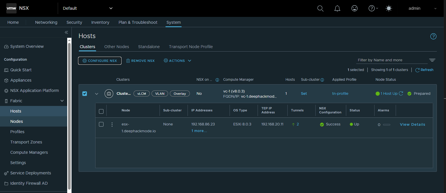
- In the Clusters tab, click the check box on the left side of the cluster.
- Click “Configure NSX” from the menu above the table.
- Select “tn-profile” as the Transport Node Profile, then click Save.
- Wait until the NSX Configuration column displays Success. You can click the Refresh button to refresh the window.
Step 4: Deploy NSX Edge Nodes and Create an Edge Cluster
Create two segments for each Edge TEP network
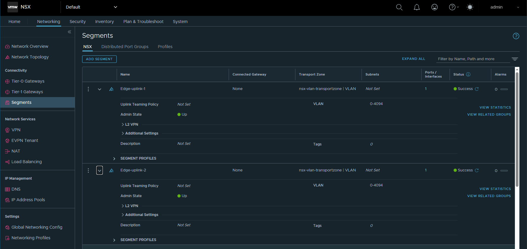
- In NSX Manager, go to Networking->Segments.
- In NSX tab, click Add Segment.
- Name the segment “Edge-uplink-1”.
- Leave the Connected Gateway as None.
- Set the Transport Zone to nsx-vlan-transportzone.
- Set VLAN to “0-4094”
- Click Save to save the segment.
- Repeat the steps to add another segment with name of “Edge-uplink-2”.
Create an IP Pool for the Edge TEP network
- In NSX Manager, go to Networking->IP Address Pools.
- Click Add IP Address Pool.
- Add “edge-tep-pool” as the Name.
- Click “Set” under the Subnets column.
- Click Add Subnet.
- Click “IP Ranges”.
- Add the IP Range “192.168.20.17-192.168.20.18”.
- Add the CIDR “192.168.20.0/24”.
- Add Gateway “192.168.20.1”.
- Click Apply to save the Subnet configuration.
- Click Save to save the IP Pool.
Create two uplink profiles for each Edge node
- In NSX Manager, go to System->Fabric->Profiles->Uplink Profiles.
- Click Add.
- In the Name field, enter Edge-uplink-1.
- Under Teamings, select Default Teaming and enter uplink1 for Active Uplinks.
- In the Transport VLAN field, enter 12.

Deploy NSX Edge Nodes
- In NSX Manager, go to System->Fabric->Nodes->Edge Transport Nodes.
- Click Add Edge Node.
-
Provide the following information.
Name Edge-1 Host name edge-1.deephackmode.io Form Factor Select the appropriate edge node size. CLI User Name admin CLI Password Allow SSH Login Select an option based on your datacenter policy. System Root Password Allow Root SSH Login Select an option based on your datacenter policy. Audit User Name audit Audit Password Compute Manager VC-1 Cluster Cluster Host 192.168.86.23 Datastore datastore1 IP Assignment Static Management IP 192.168.86.252 Default Gateway 192.168.86.34 Management Interface “VM Network” DNS Servers 192.168.86.34 NTP Servers 192.168.86.34 Edge Switch name nvds1 Transport Zone nsx-overlay-transportzone, nsx-vlan-transport-zone Uplink Profile Edge-uplink-1 IP Assignment Use IP Pool IP Pool edge-tep-pool DPDK Fastpath Interfaces Click Select Interface and select the VLAN Segment “Edge-uplink-1” 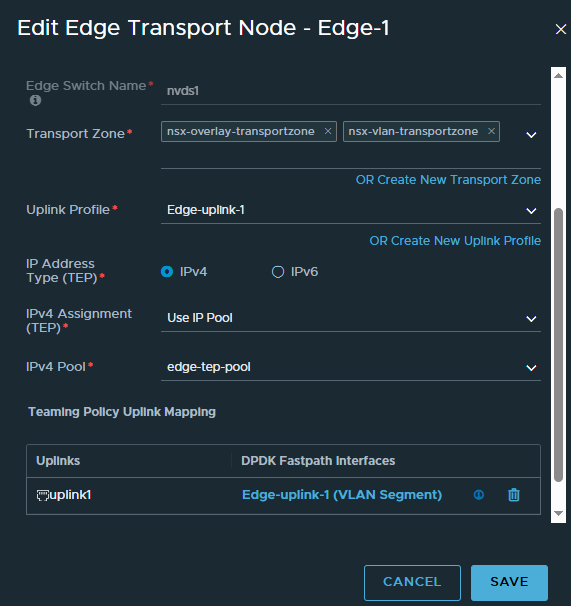
- Wait until the Configuration State column displays Success. You can click the Refresh button to refresh the window.
-
Repeat steps 2-4 to deploy Edge-2, using the following information.
Name Edge-2 Host name edge-2.deephackmode.io Form Factor Select the appropriate edge node size. CLI User Name admin CLI Password Allow SSH Login Select an option based on your datacenter policy. System Root Password Allow Root SSH Login Select an option based on your datacenter policy. Audit User Name audit Audit Password Compute Manager VC-1 Cluster Cluster Host 192.168.86.23 Datastore datastore1 IP Assignment Static Management IP 192.168.86.253 Default Gateway 192.168.86.34 Management Interface “VM Network” DNS Servers 192.168.86.34 NTP Servers 192.168.86.34 Edge Switch name nvds1 Transport Zone nsx-overlay-transportzone, nsx-vlan-transport-zone Uplink Profile Edge-uplink-2 IP Assignment Use IP Pool IP Pool edge-tep-pool DPDK Fastpath Interfaces Click Select Interface and select the VLAN Segment “Edge-uplink-2” 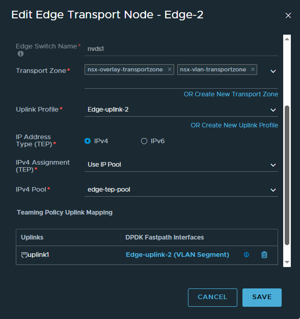
- Wait until the Configuration State column displays Success
Create an Edge Cluster
- In NSX Manager, go to System->Fabric->Nodes->Edge Clusters.
- Click Add Edge Cluster.
- In the Name field, enter “Edge-cluster-1”.
- Move Edge-1 and Edge-2 from the Available window to the Selected window.
- Click Add.
Step 5: Configure Gateways and Segments
Create a VLAN Segment to Connect to the Physical Router
- In NSX Manager, go to Networking->Segments.
- Click Add Segment.
-
Provide the following information.
Segment Name External-segment-1 Connected Gateway None Transport Zone nsx-vlan-transportzone VLAN 50
Create a Tier-0 Gateway
- In NSX Manager, go to Networking->Tier-0 Gateways.
- Click Add Tier-0 Gateway.
- Enter a name for the gateway, for example, T0-gateway-1.
- Select the HA (high availability) mode Active Standby.
- Select the Edge cluster Edge-cluster-1.
- Click Save and continue configuring this gateway.
- Click Interfaces and click Set.
- Click Add Interface.
- Enter a name, for example, IP1-EdgeNode1.
- Enter the IP address 192.168.50.11/24.
- In the Connected To (Segment) field, select External-segment-1.
- In the Edge Node field, select Edge-1.
- Save the changes.
- Repeat steps 8-13 to configure a second interface called IP2-EdgeNode2. The IP address should be 192.168.50.12/24. The Edge Node should be Edge-2.
- In the HA VIP Configuration field, click Set to create a virtual IP for the tier-0 gateway.
- Enter the IP address 192.168.50.13/24.
- Select the interfaces IP1-EdgeNode1 and IP2-EdgeNode2.
- Save the changes.
- Configure Routing on the Physical Router and Tier-0 Gateway
- On the physical router, configure a static route to the subnets 10.1.1.0/24, 10.1.2.0/24, and 10.2.1.0/24 via 192.168.50.13, which is the virtual IP address of the tier-0 gateway’s external interface.
- In NSX Manager, go to Networking->Tier-0 Gateways.
- Edit T0-gateway-1.
- Under Routing->Static Routes, click Set and click Add Static Route.
- In the Name field, enter default.
- In the Network field, enter 0.0.0.0/0.
- Click Set Next Hops.
- In the IP Address field, enter 192.168.50.1.
- Click Add.
- Save the changes.
Create Two Tier-1 Gateways
- In NSX Manager, go to NetworkingTier-1 Gateways.
- Click Add Tier-1 Gateway.
-
Provide the following information.
Tier-1 Gateway Name T1-gateway-1 Edge Cluster Edge-cluster-1 Linked Tier-0 Gateway T0-gateway-1 - Under Route Advertisement, enable All Connected Segments & Service Ports.
- Save the changes.
- Repeat steps 2-5 and create T1-gateway-2. Specify the same edge cluster.
Create Three Overlay Segments for VMs
- In NSX Manager, go to Networking->Segments.
- Click Add Segment.
-
Provide the following information.
Segment Name LS1.1 Connected Gateway T1-gateway-1 Transport Zone nsx-overlay-transportzone Subnets 10.1.1.1/24 Note: For an overlay segment that is attached to a tier-1 gateway, in the Subnets field, specify an IP address for the tier-1 gateway. This address will be the default gateway for VMs attached to this segment.
- Repeat steps 2-3 and create LS1.2 (Subnets: 10.1.2.1/24, Connected Gateway: T1-gateway-1) and LS2.1 (Subnets: 10.2.1.1/24, Connected Gateway: T1-gateway-2).
- Verify that LS1.1, LS1.2, and LS2.1 are created under the appropriate VDS in VC.
At this point, check the Edge nodes at Fabric->Nodes->Edge Transport Nodes. The nodes should have at least 2 tunnels showing up (green).
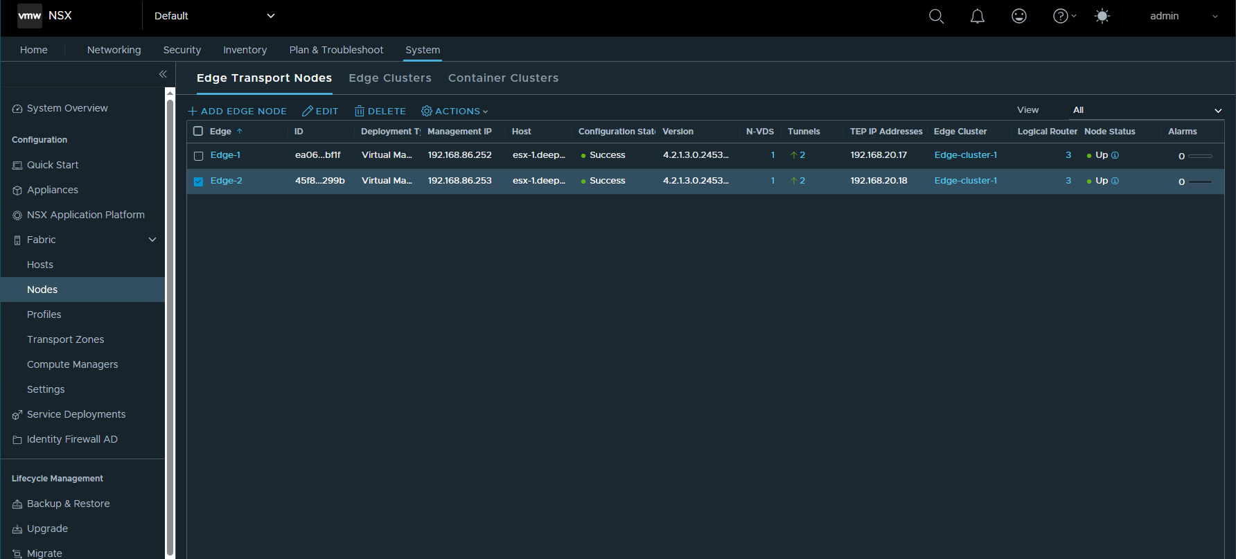
Step 6: Test East-West and North-South Connectivity
- Deploy a test VM in each of the 3 segments.
- Assign each one an IP address
- From each VM, ping the other Test-VM’s and make sure that they are successful, and if so then that means that East-West connectivity is working.
- From each VM, ping the Tier-0 gateway IP address 192.168.50.13 and external router (192.168.50.1). If that was successful, then that meanst that North-South connectivity is working.